Vélo Québec recommends a width of 3 metres for a two-way bike path on a dedicated right-of-way, i.e. 1.5 metres per direction. With its 3.20 m path, the tunnel meets and exceeds this Québec standard. This page presents two configurations: the standard geometry of the Prufrock boring machine, and a variant where the floor is lowered by 10 cm to gain height — without changing the boring diameter or the costs.
1. The standard configuration (Prufrock 3.66 m)
Specifications
- Inner diameter: ≈ 3.66 m (12 ft — The Boring Company's Prufrock standard)
- Path width: 3.20 m (1.6 m per direction)
- Floor width: 3.48 m
- Margin (shoulder): ~14 cm on each side
- Clear height: 2.30 m usable (2.40 m to the concrete)
This geometry lets you comfortably pass another user, accommodate an electric scooter or a mobility scooter, and reserve the space above for ventilation and lighting.
The 3.66 m diameter matches the standard of the Prufrock boring machine, which simplifies boring and reduces costs.
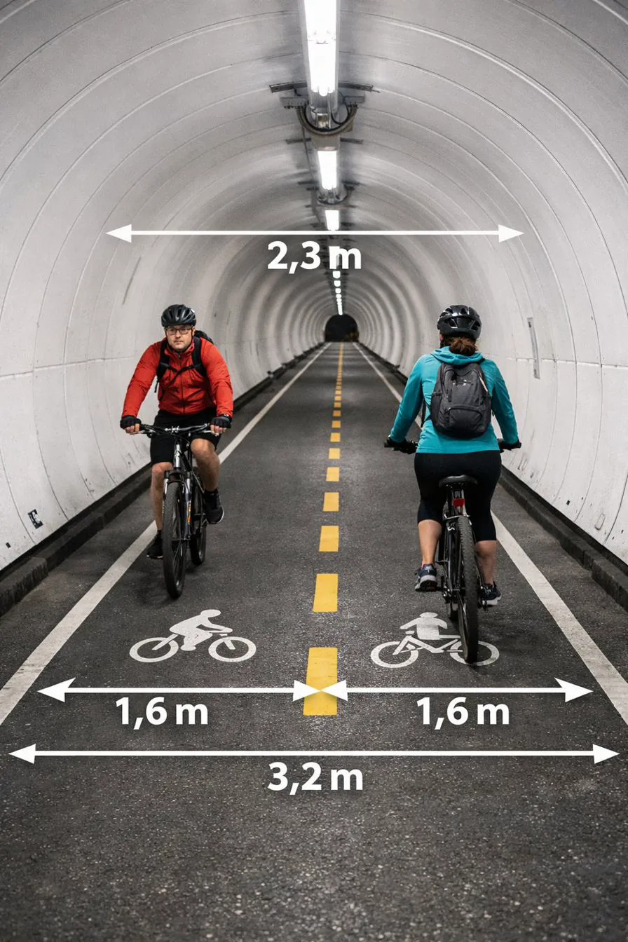
Compliant with Québec standards — and beyond. Vélo Québec
recommends a width of 3.0 m (1.5 m per direction) for a two-way bike path
on a dedicated right-of-way, with a tolerated minimum of 2.5 m over short
constrained stretches. The tunnel's 3.20 m path meets and
exceeds this recommendation — in both configurations presented below.
Source: Vélo Québec, Aménagements en faveur des piétons et des cyclistes — Guide technique.
2. Why the height is not constant
The ceiling is circular: the clear height is greatest at the centre and decreases towards the walls. It's purely geometric. The cross-section below shows the clear height to the concrete (in green) at several positions along the horizontal X axis, where X = 0 corresponds to the central axis.
3. The « floor lowered by 10 cm » variant
By building the running slab 10 cm lower in the same bored tube, we recover 10 cm of clearance everywhere — without touching the diameter or the boring costs. The floor narrows slightly, but the 3.20 m path holds with a still-comfortable margin.
Floor width (chord of the circle).
Unchanged — margin ~10 cm on each side.
To the concrete (≈ 2.40 m usable).
Void under the floor — amply sufficient.
4. Comparison of the two configurations
| Characteristic | Standard | Floor −10 cm |
|---|---|---|
| Inner diameter | 3.66 m | 3.66 m |
| Floor depth (below the axis) | 0.57 m | 0.67 m |
| Floor width | 3.48 m | 3.41 m |
| Bike path width | 3.20 m | 3.20 m |
| Margin (shoulder) per side | ~14 cm | ~10 cm |
| Height at centre (concrete) | 2.40 m | 2.50 m |
| Usable clear height (under lighting) | 2.30 m | 2.40 m |
| Height at path edge | 1.46 m | 1.56 m |
| Drainage space at centre | 1.26 m | 1.16 m |
5. Clear height along the X axis
Clear height to the concrete, from the centre (X = 0) towards the wall, for the two configurations. A cyclist normally rides at the centre of their lane, around X = ±0.8 m.
| Position X (from the axis) | Standard | Floor −10 cm |
|---|---|---|
| 0 m — central axis | 2.40 m | 2.50 m |
| ± 0.2 m | 2.39 m | 2.49 m |
| ± 0.4 m | 2.36 m | 2.46 m |
| ± 0.6 m | 2.30 m | 2.40 m |
| ± 0.8 m — centre of a lane | 2.22 m | 2.32 m |
| ± 1.0 m | 2.10 m | 2.20 m |
| ± 1.2 m | 1.95 m | 2.05 m |
| ± 1.4 m | 1.75 m | 1.85 m |
| ± 1.5 m | 1.62 m | 1.72 m |
| ± 1.6 m — path edge | 1.46 m | 1.56 m |
The lowered variant adds exactly +10 cm to each row. The height decreases towards the wall because the ceiling is round; at the centre of each lane (X = ±0.8 m), the clearance remains amply sufficient in both cases.
6. Why can the floor be lowered?
When you lay a flat floor in a round hole, a crescent of space necessarily remains below it. In the standard configuration, this void reaches ~1.26 m deep at the centre — far more than strictly necessary.
What this space is for
It is not wasted: it houses the drainage channel (infiltration water and condensation are collected there, then pumped out), the cable run (electricity, fibre, lighting, emergency systems) and the structural backfill that supports the running slab. The drainage is serious: pumping out the groundwater table already represents about 9,000 MWh/year in the operating budget, because the tunnel passes in places below the water-table level.
The key principle: lowering the floor by 10 cm raises the clear height by 10 cm at all X positions at the same time — at the centre as well as at the edge. In the height formula, h(x) = √(R² − x²) + d, the floor depth d is a constant that adds everywhere. The edge, which was the tightest point, therefore gains as much as the centre.
What limits the lowering
It's not the drainage — it's the path width. As it descends, the floor (a chord of the circle) narrows. To keep the 3.20 m path with a comfortable margin, 10 cm is a prudent lowering; the absolute limit (zero margin) sits around 32 cm. Even lowered by 10 cm, there remains ~1.16 m of void at the bottom — plenty of room to house the channel and the cables.
✓ What we gain
- +10 cm of clear height everywhere along the X axis
- No larger machine, no extra boring cost
- A little less backfill to put in place
- Enlarged air section above the path (better ventilation)
To consider
- Reduced lateral margin: ~14 cm → ~10 cm per side
- Slightly more vertical walls near the ground (rather pleasant on a bike)
- Keep the drainage invert at the bottom — amply the case here
10 cm gained, for free.
The lowering gives +10 cm of clearance along the entire X axis, keeps the path at 3.20 m and preserves the drainage — without ever touching the boring diameter or the economics of the project.
Normative benchmark: cycling-tunnel guidelines target ~2.30 to 2.50 m of clear height (CROW, Netherlands; LTN 1/20, United Kingdom). Both configurations meet this minimum at the centre; the lowered variant simply offers a more generous margin. Values calculated for an inner radius R = 1.83 m (Ø 3.66 m); preliminary figures to be confirmed in detailed engineering.